Testing
Hardware
Before we combined the control unit with the other components, we did a lot of testing.
Most of our tests were unit tests, the unit being the control unit. We simulated all other parts and tested that the control unit produces the correct outputs, for the correct inputs. So we tested every cable and signal if for all inputs the correct result for the control lines is outputted.
For that we wrote the file control_testbed.py and also mega_programm.ino.
The latter was for an Arduino Mega (thus its name), which was connected to the control unit. The first program runs on a normal computer and communicates with the Arduino over the USB-to-serial bridge. It sends some bytes to the Arduino, which then outputs these over the Arduino's GPIO pins (and therefore sets the inputs for the control unit). After that, the Arduino waits some milliseconds and then reads its inputs (therefore the outputs of the control unit). The read signals are then forwarded to the computer.
The program control_testbed.py uses the HDL model of the control unit.
It simulates the control unit using this model, and feeds the same inputs to both the software model and the hardware control unit.
It then checks that both produce the same output.
The program also simulated the different clock domains, checking that the correct outputs are set at every half clock-cycle.
Our first test suite then simply emitted random values onto the BUS and FLAGS input to the control unit every time. Later, we wrote more refined test suites, which simulated precise instructions and more complicated scenarios like interrupts and prefix_a16 instructions.
This approach enabled us to rather quickly (about 50 milliseconds per clock cycle) test lot of random scenarios. Of course, this test suite did not cover all possible inputs. We later tried to increase coverage by executing all sequences of length 2. While full coverage is possible in theory, it would require testing each of the 17 input bits, and also the 6 bits of internal state, which would take about a week.
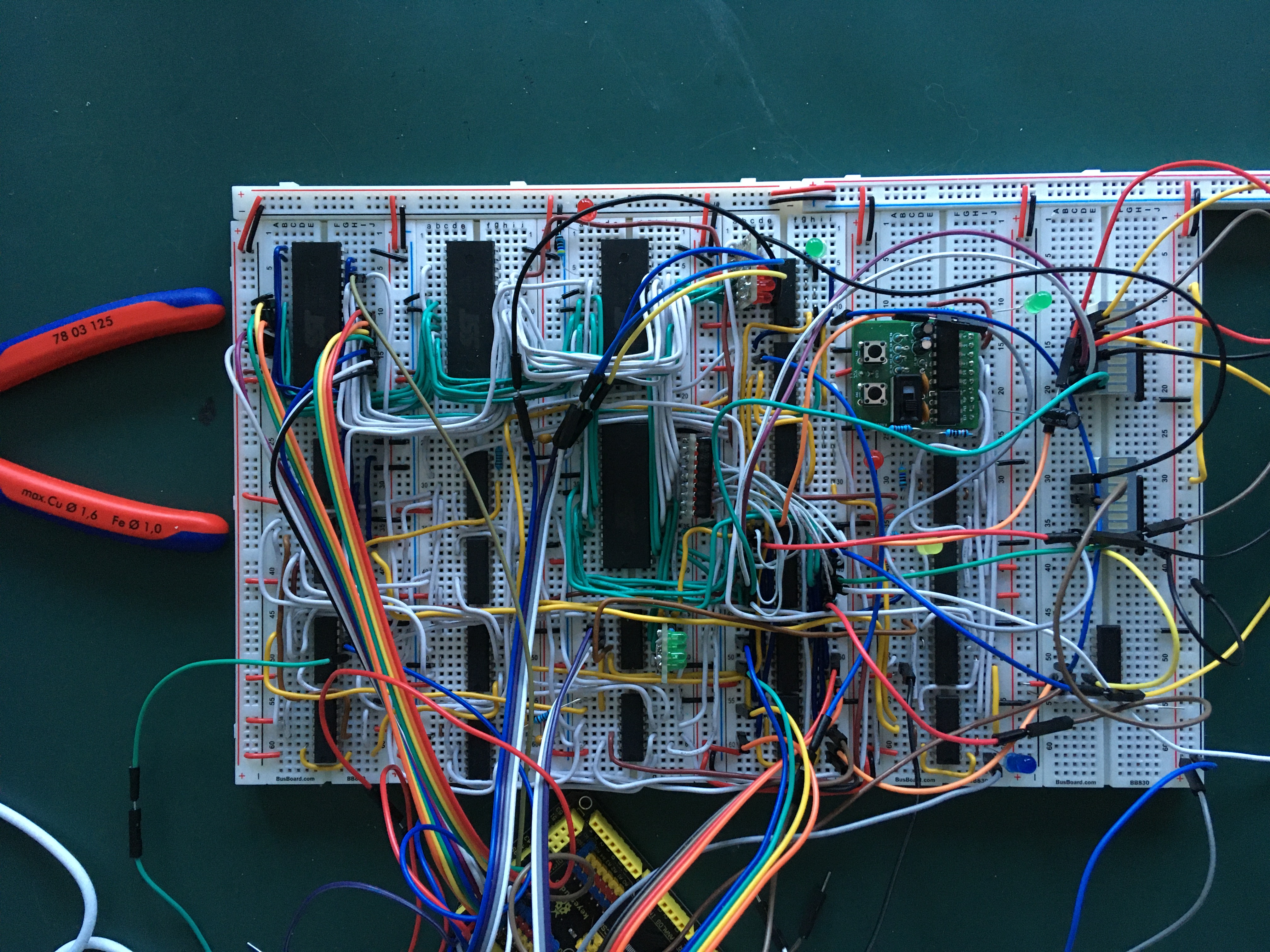
Here you can see a picture and video of the control unit in time of unit testing.
This testing approach allowed us to find several bugs in the control unit, like missing or wrongly connected cables. Other bugs that were more nasty to fix were timing issues in several chips, which led to them reading the wrong value sometimes. Those bugs often felt like "Heisenbugs", since they only appeared under certain circumstances.
We also noticed that the HDL model of the control unit was not complete. In the end, our testing was very useful to make sure that both the HDL model and the physical build have the same behavior. This allowed us to place more trust on the HDL model, and to find bugs in the microcode a lot easier since we could simulate (and debug) the microcode on a computer, instead of a breadboard.
Microcode
For debugging the microcode, the HDL model proved to be very useful as well.
By using the assertz instruction in more or less simple programs (isa-test-*.s in the isa directory), we discovered several bugs.
One of the advantages of the HDL emulator is that all registers etc. are directly visible.
This is not the case for the real build, because the register chips (74-670) can output only one register at a time.
Furthermore, the microcode does not need to be flashed on four chips before a new version can be tested.
The test suite, however, is not perfect yet.
The tool run-isa-tests.sh automatically generates statistics how often which microcode snippet was executed.
It turns out that some instructions have not been tested yet.
Furthermore, it would be interesting to check whether prefixed instructions work as expected.
Therefore, the HDL model needs to be extended by dummy IO devices.