Control Unit
The control unit was mainly developed by Johannes Hostert, Nils Husung, Iona Kuhn and Marvin Meiers. Major contributions to the microcode were also made by Florian Bauckholt. The unit is in working condition and has been integrated into the final build.
Overview
The control unit controls the processor, by setting control lines which modify the behavior of all other parts of the processor. For example, there are control lines directing several parts to read from or write to the data bus, or to direct the ALU what kind of operation it should execute. The control unit also contains the clock, which synchronizes all parts. It maintains several important latches which influence the overall behavior of the processor, like whether an interrupt is currently being handled.
The control unit foremost provides a bare-metal execution environment for microcode, which is implemented directly in hardware. The operation and programming model of this hardware execution environment is what we call the µISA.
With the µISA settled, we wrote microcode that implements the SaarCPU ISA. The microcode is responsible for setting the correct control lines for each instruction. It can be changed by flashing the memory chips on the control unit, however this involves physically removing them from the breadboard.
Schematics and Chip Layout


The upper four breadboards contain the main control logic while the breadboard at the bottom contains the clock and reset module. The empty space at the bottom right of the chip layout figure is occupied by the power supply and knoepfchen in the build. Knoepfchen is a small PCB containing a TLC555 timer as well as two buttons and a switch.
This documentation is split into several parts. On the clock page, we go into more detail about the clock and reset module. In particular, we describe which clock is used by which part. The page also includes the schematic. A detailed overview of external and internal control lines (where internal control lines control the control unit itself) can be found in control lines. In microcode, we describe how we programmed the microcode to execute the specified ISA. In µISA, we describe the hardware of the control unit, i.e. how it executes microcode.
Lessons Learned
- We noticed that breadboards are not ideal.
You should, after you put some cables or a chip in, always measure if they are properly connected.
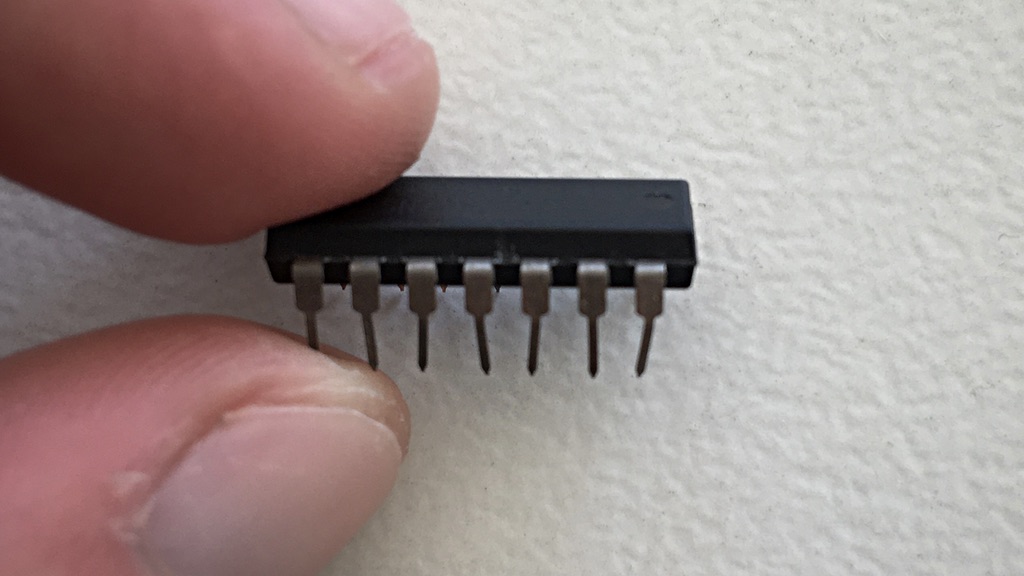
If not, just bend the contacts of the chip alternating to the left and the right, like in the following picture:
- Trying to build a reset logic around a 74-377 (8-bit register) is usually not a good idea. We spent a lot of time on debugging and fixing problems with our initial version and eventually decided to use two 74-173 (Quad D-Flip-flops) instead. This also reduced the number of chips needed.
- Be careful about clock signals.
Applying simple logical operations to them (e.g. AND with another signal) may be dangerous.
In one case, we wanted to have a signal that is active only during the first half cycle.
It was tempting to feed it through an AND gate along with
CLK. However, as the control lines need some time to settle, the signal was also active at the beginning of the next cycle. To fix this, we introduced a delayed variant of the clock and built a signal that gets active shortly after the control lines stabilize and inactive at the rising clock edge. This is currently built on the decoder board of the Mem/Regs unit. - Another issue related to clock signals is to feed “non-clock signals” into clock inputs.
We previously fed the decoder output directly into the clock inputs of some 74-74s (Dual D-Flip-flop) to toggle them.
As the flash chips need some time for their outputs to stabilize, the clock input was triggered during this phase, although it should not have been.
This is the reason why we enable one of the decoders only when
CLKis high.
In a different case, we had some sort of edge detector in our circuit (which we were not aware of). This also caused an unwanted clock pulse at an 74-74. - Writing microcode is error-prone. Carefully think about the framework and add many static sanity checks.