Overview

Interrupts
TODO
Roadmap
- PS2 Keyboard
- Timer
- SPI, SD-Card
- Sound card
- Real-Time-Clock
- MIDI (via FPGA)
- Barcode Scanner (RS232 protocol)
- GPIO
- IO Break Out-Board
ISA
For further details see ISA Overview.
| Mnemonic | Description |
|---|---|
prefix_a16 | change addressing mode to memory mapped IO for the next instruction |
i2c_send | Send data over I2C |
i2c_recv | Receive data over I2C |
spi | send and receive for SPI communication |
Control Lines
Note: We use ~ to denote active-low control lines. All other control lines are active-high.
Parallel
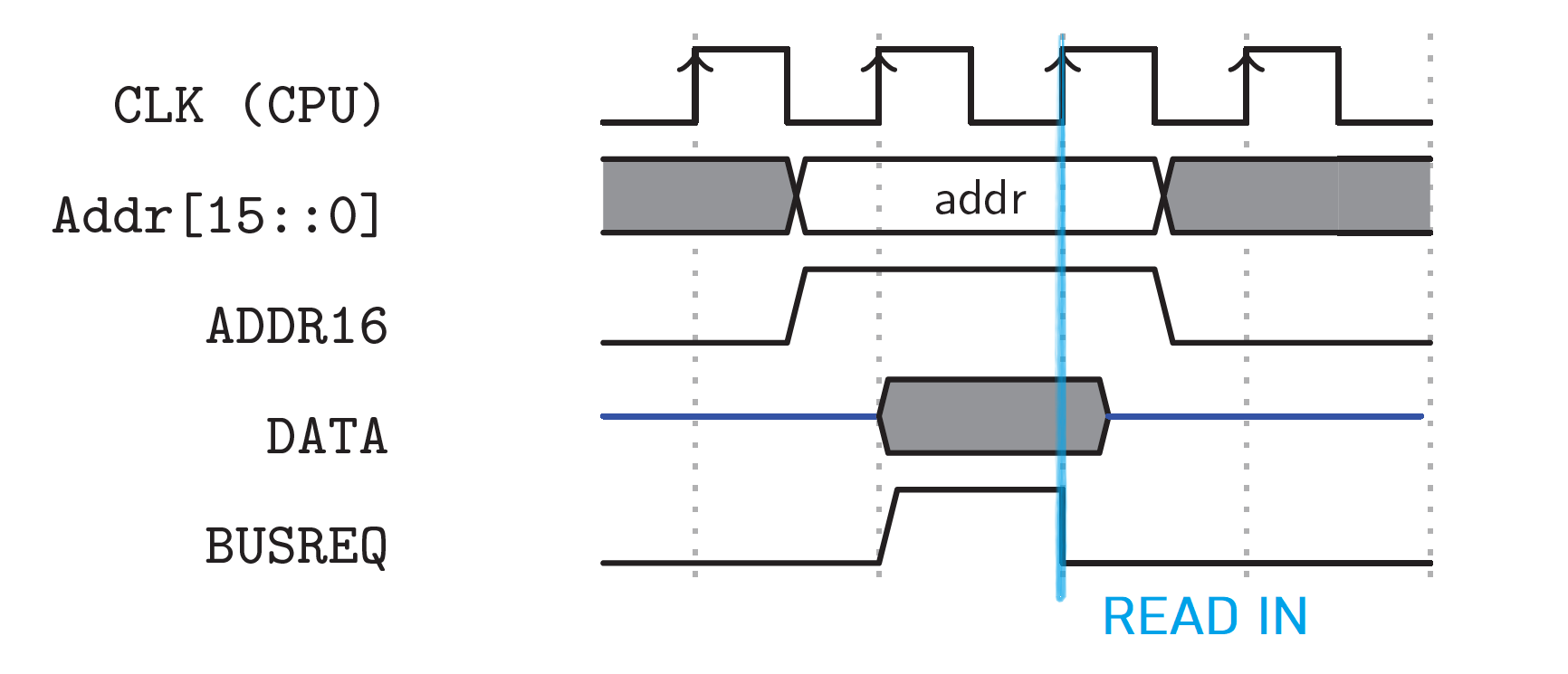
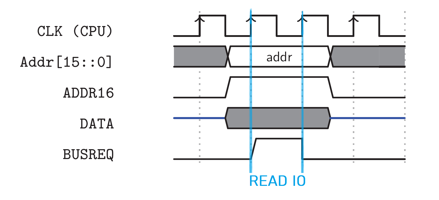
~INT: Signals CPU interrupt from IO-device.INTACK: Signals acknowledgement from CPU to IO-device. Commences interrupt handling routine.IO/MEM_TO_DBUS: Memory Write From BusIO/MEM_FROM_DBUS: Memory Read From BusADDR16: Shared with Graphics to differentiate between MMIO and normal address space. The 17th address bit, so to say.BUSREQ: Signals CPU that IO-device wants to access data bus for read/write operation.
For case IO to CPU:
 For case
 CPU to IO:
Serial (for SPI/I2C)
SPI_SEND/REC: For sending and receiving data via SPI communication.SPI_SCLK_EN: Enables clock of SPI device to make SPI communication possible according to SPI protocol.
IO Address Ranges
| Address | Device |
|---|---|
0x0000 | reserved |
0x0001 | Arduino |
0x0008-0x000f | Keyboard |
0x0100-0x01ff | Timer |
0x8000-0xffff | Graphics-Card |