Soundcard
This part is only a concept. We will most likely not be able to build and integrate it.
Participators: Ferdinand, Johannes K.
Soundcard
Our construction consists of one physically realized voice and an arbitrary number of other voices simulated in an FPGA (Intel Cyclone V) in order to save chips. A list of all projected required parts including if more than one voice was realized physically can be found here.
TODO: upload file and covert link
Furthermore the soundcard is supported by our timer module to allow for simpler MIDI Playback.
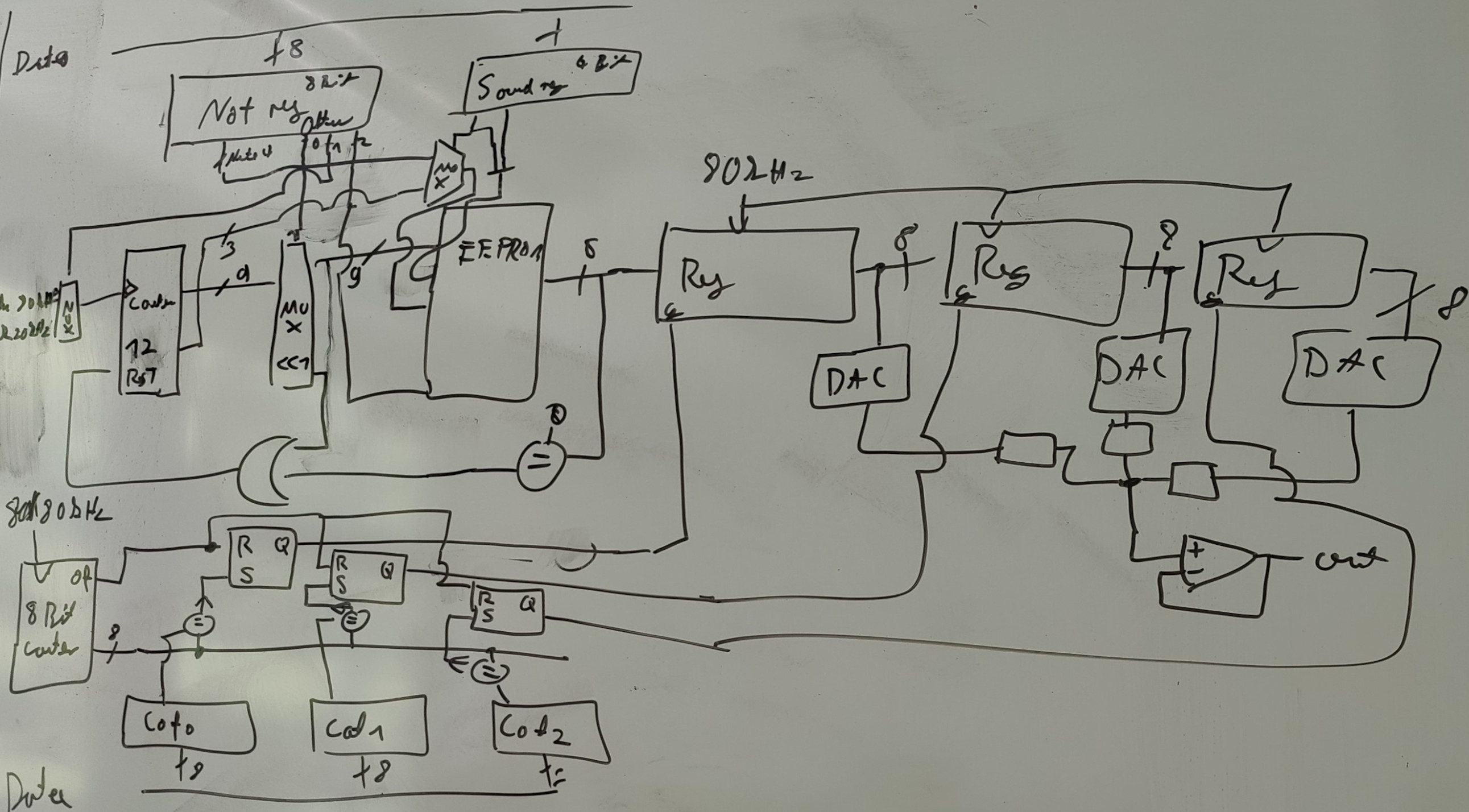
Core Ideas
- Timer signals the CPU to input new data into the soundcard
- FPGA generates 80kHz and 20kHz clock signals.
- FPGA also contains more voices.
- Flash chip contains waves (sine, square, triangle and sawtooth waves), which are chosen together with the octave, the waveform and note.
- FIR (finite impulse response) Filter filters the frequencies and regulates the volume with PWM signals.
- Digital signals are converted to analog signals with a DAC
- Adding the analog signals together to get the final signal
Schematics
TODO add KiCad schematics
A more detailed explanation can be found in the slides.
Note Selection
Note
The 12 possible notes are encoded into 4 bits, whereby 0b0000 encodes the lowest playable note depending on the input clock rate (the Flash script does output the mapping).
Octave
The 8 playable octaves are encoded into 3 bits. The lowest bit shifts the counter output by one, effectively skipping every second sample. This lifts the octave by one. The second bit switches to a 4 times higher clock input and lifting the octave by 2. The third bit switches to a 4 octave higher version of the waveform.
Flash Program
Address layout waveforms:
| Bits | Name | Description |
|---|---|---|
| 0-8 | Sample | Selects a sample out of the waveform |
| 9-11 | WAVindex | Selects a waveform or Sample |
| 12-15 | Note | Selects a note in one Octave (A0+minTone+Note) |
| 16 | Shift | Selects between the tone and a 4 Octave higher version |
Address layout Drum Samples:
| Bits | Name | Description |
|---|---|---|
| 0-8 | Sample_Low | Selects a sample out of the Drum Sample(Lower bits) |
| 9-11 | WAVindex | Selects a waveform or Sample |
| 12-15 | Sample_High | Selects a sample out of the Drum Sample(higher bits) |
| 16 | HighV | Selects a secondary Drum Sample that is stored where the higher version of the waveforms would be |
| WAVindex | Waveform/sample |
|---|---|
| 0 | Sine wave |
| 1 | Square wave |
| 2 | Triangle wave |
| 3 | Sawtooth wave |
| 4a | Snare (20Khz) |
| 4b | High Noise (40Khz) |
| 5a | Base (20Khz (also good on 40Khz)) |
| 5b | Tom (20Khz) |
| 6a | High Hat closed (20Khz) |
| 6b | empty |
| 7a | empty |
| 7b | empty |
See here for the python script.
Software
A simulation in form of a VST Plugin to for DAWs exists but is not shared here due to License issues with used software and sounds.
Addressing
Address range not yet fixed
Testing
Due to time limitations we will not be able to build, and therefore test, the soundcard. It is only a concept for now.
Findings
- How simple sound synthesis works
- How to use pulse width modulation for analog multiplication
- How to design FIR Filters
- How to write VST-Plugins