Microcode
The microcode is stored in the four ROM chips. As mentioned in the documentation on the µISA, there is a sequence of up to 16 microinstructions (control words) executed for each possible combination of flags, interrupt pending state, and instruction opcode. Most opcodes do not care about the flags, and thus have the same microcode repeated 16 times for each possible combination of flags. The microcode for handling interrupts is repeated very often, since it is almost always executed when the interrupt pending flag is enabled, irrespective of the other inputs. While this seems to waste a lot of space, it also radically simplifies the design of the control unit.
The file microcode.py defines the microcode instructions for each ISA instruction.
We then have two additional programs (microcode_to_bin.py and microcode_to_csv.py) that export these as a binary or CSV file.
The binary files then can be flashed on the ROM chips.
The CSV file is used by the µArch Simulator.
The microcode maintains several invariants across the execution:
- The PC value is always stored in the address latch. If an instruction needs to otherwise use the address latch, it first needs to move the PC from the address latch to the proper register.
- The PC value (in the address latch) does not actually point to the current instruction’s opcode when it starts executing it, but to the byte immediately after it (which might be the immediate or a new instruction). This is because the instruction fetch is initiated by the previous instruction, which already increases the address latch.
- The stack pointer points to the last valid byte on the stack.
- The shadow registers
W,X,Y, andZare used to save the PC, the accu and flags during an interrupt. They may not be used as temporaries. - The shadow registers
UandVare available as temporaries.
We now document the actual microcode, to be found in microcode.py.
Writing Microcode
A microcode word has 32 bits, of which 25 directly drive control lines or internally modify the control unit (compare with the µISA documentation). Four other control lines are decoded through a 4-to-16 decoder (consisting of two 74-138, 3-to-8 decoders). When writing microcode, this decoder is abstracted away, and we can write our microcode as if the outputs were individual control lines. A static analysis pass ensures that these control lines are always mutually exclusive. The static analyzer also checks for other simple errors like whether all instructions end in an instruction fetch.
The three remaining control word bits drive six control lines, each driving two at a time, where one of those is always “don’t care.”
When writing microcode, a control line can have three assigned values: “positive” (or p, i.e. active), “negative” (or n, i.e. not active), or “don’t care.”
We then have code that looks for such pairs where one is always “don’t care” when another is active, so that we could merge them.
A control word is then specified by describing which control lines are p or n.
This is added to a baseline of control words, so that we have a default that does not need to be specified all the time (e.g. reset_uinst_counter is almost never enabled).
nop
instruction("nop", opcode(0xff), [])
That’s it, that’s the instruction. It seems like a nop actually does nothing. Yet, there is more to the picture here, than meets the eye.
The instruction function takes a name ("nop") to ease debugging, a generator which yields the start addresses of the instruction (opcode(0xff)) and a list of control words ([]).
opcode(0xff) yields addresses with opcode 0xff, all different SZVC-flag combinations and no interrupts.
The empty list here indeed specifies that the instruction does not do anything useful.
However, the instruction still needs to advance the PC and fetch the next instruction.
This is so common that we usually append instruction_fetch to the array of control words.
Only if auto_if=False is passed to the instruction function, this is disabled.
The instruction_fetch control word is defined as follows:
postincrement_addr = p(CLine.reg_latch_count | CLine.reg_latch_up)
instruction_fetch = p(CLine.reset_uinst_counter) | postincrement_addr
An instruction fetch works by asserting reset_uinst_counter, which also implicitly loads from memory to the opcode register, and by setting reg_latch_count and reg_latch_up, so that the address latch counts up.
This counting-up is delayed so that it happens after the load, hence it is a post-increment.
As noted above, the latch was already pointing at the next instruction.
Setting auto_if=False can be useful in a few cases to perform actions along with the instruction fetch.
Note however that the data bus is already used to fetch the instruction.
This is why most instructions cannot be further optimized by manually extending the instruction fetch control word.
reset
# reset initializes, the PC, SP and accu to 0, clears all flags and disables# interruptsinstruction("reset", ( 0x00 << OPCODE_LSB | flags << FLAGS_LSB for flags in range(1 << 5)), [ # just a µNOP to ensure that we do not start with only a half cycle CState(), # load zero into accu ("reset" interrupt code) clear_alu_latch | CState( # clear flags p=(CLine.alu_set_flags_raw | CLine.alu_update_flags), n=(CLine.alu_use_shadow_carry | CLine.alu_update_just_carry | CLine.alu_zero_flag_and) ), clear_alu_accu | p(CLine.set_interrupt_inhibit) | CState( # clear shadow carry p=(CLine.alu_set_flags_raw | CLine.alu_update_flags | CLine.alu_use_shadow_carry), n=(CLine.alu_update_just_carry | CLine.alu_zero_flag_and) ), # clear PC and SP UarchReg8.PC_LO.from_dbus() | zero_to_dbus, UarchReg8.PC_HI.from_dbus() | zero_to_dbus, UarchReg16.PC.to_addr() | UarchReg16.SP.from_addr() | instruction_fetch,], auto_if=False)The reset instruction is special because it is not blocked by interrupts. Its opcode is 0x00, since this is what the hardware reset resets the opcode register to. Since it also needs to happen on interrupts, we manually specify all addresses at which it needs to happen.
When coming out of a reset, the control unit thus starts executing the control word at 0x00000 (17-bit address), which is a control no-op, such that no control lines are asserted (line 7).
The reason for this is that the instruction and flags register, as well as the microinstruction counter have an asynchronous reset.
When operating at a low clock speed, the reset signal might well be active only during the second half cycle.
In this case, the actions that would normally happen at a rising clock edge will not happen.
We then continue:
- Line 9-14: We clear the ALU latch, and set the flags from the data bus. The
dbusis always set to zero if no one else is writing to it, so this zeros the flags, which might still be undefined since they have not been cleared yet. - Line 15-20: We zero out the accu, inhibit interrupts, and also set the shadow flags. Note that here,
alu_use_shadow_carryispinstead ofn, so it is cleared as well. - Line 21-22: We clear the PC.
- Line 23: We continue to clear the PC.
- Line 24: We move the PC to the address latch, and the SP from the address latch. Since these registers are all level-triggered, the 0 from the PC propagates to both the SP and the address latch. Also, we run an instruction fetch afterwards.
- Line 25: Since we already ran the instruction fetch while also zeroing the PC, we do not need to automatically add it.
call imm16
load_imm = p(CLine.imm_load) | postincrement_addrpostdecrement_addr = CState(p=CLine.reg_latch_count, n=CLine.reg_latch_up)instruction("call imm16", opcode(0b00_001_001), [ # set the PC register to the immediate ("old" PC remains in address latch) load_imm | UarchReg8.PC_LO.from_dbus(), load_imm | UarchReg8.PC_HI.from_dbus(), UarchReg16.UV.from_addr(), # PC to shadow register 1 UarchReg16.SP.to_addr() | postdecrement_addr, # U corresponds to PC_HI, push hi first to have LE UarchReg8.U.to_dbus() | dbus_to_mem | postdecrement_addr, UarchReg8.V.to_dbus() | dbus_to_mem | UarchReg16.SP.from_addr(), UarchReg16.PC.to_addr() | instruction_fetch,], auto_if=False)- Line 6: We use
load_imm(defined in line 1) to load an immediate from memory, and increment the PC (which is already pointing to the immediate and stored in the address latch) right after loading. The immediate is loaded into the lower half of thePCregister. Note that program execution is not diverted yet, we're not fetching the next instruction yet. - Line 7: We do the same for the upper half. Immediately afterwards, the address latch will point at the next instruction, i.e. where the return should go to.
- Line 8: We save the return address in the temporary shadow register
- Line 9: We move the SP, which currently points at the last valid stack entry, to the address latch, and decrement it immediately afterwards. The latch now points at the first free stack address.
- Line 12: We store
U, i.e. the old upper PC, in memory. Since the stack grows down, this corresponds to little-endian. Also, we decrement the latch right after. - Line 13: We store
V, and move the latch back to the stack pointer, so that its register contents have effectively decreased by two. - Line 14: We move the PC, which contains the call target, to the latch, and execute an instruction fetch.
Interestingly, storing UV on the stack means that they will be stored in IO memory if this instruction is executed with the prefix_a16 latch set. We do not consider this a bug.
push
for i, reg in enumerate(IsaReg8): instruction(f"push {reg.name}", opcode(0b00_000_100 | i << 3), [ UarchReg16.PC.from_addr(), UarchReg16.SP.to_addr() | postdecrement_addr, reg.value.to_dbus() | dbus_to_mem | UarchReg16.SP.from_addr(), UarchReg16.PC.to_addr() | instruction_fetch, ], auto_if=False)The push instruction is defined several times, once for each of the ISA registers. Two special commands working similarly can push the accu, or the flags.
- Line 3: We move the PC out of the address latch, so that we can use it otherwise.
- Line 4: We move the SP to the address latch, and decrement it, so that it points at the first free stack address
- Line 5: We move the register to be pushed onto the data bus, and execute a store.
- Line 6: We move the PC back and execute an instruction fetch.
jcc imm8s16
def matches_jmp_cond(flags: int, cond: int) -> bool: sf = (flags >> SF_NUM) & 1 zf = (flags >> ZF_NUM) & 1 of = (flags >> OF_NUM) & 1 cf = (flags >> CF_NUM) & 1 return [ of, # overflow cf, # below zf, # equal cf | zf, # below or equal sf, # sign 1, # unconditional sf ^ of, # less (sf ^ of) | zf, # less or equal ][cond] == 1jcc_jump_start = [ # imm8 to latch load_imm | dbus_to_alu_latch, # save (next) pc to regs UarchReg16.PC.from_addr(), # add immediate lower UarchReg8.PC_LO.to_dbus() | alu_add_shadow, alu_latch_to_dbus | UarchReg8.PC_LO.from_dbus() | p(CLine.reload_flags | CLine.alu_use_shadow_carry),]jcc_fallthrough = [ postincrement_addr, # skip imm8s16 instruction_fetch,]assert len(jcc_fallthrough) <= len(jcc_jump_start)instruction("jcc imm8s16", ( (0b00_000_110 | c << 3 | n) << OPCODE_LSB | f << FLAGS_LSB for c in range(8) for f in range(16) for n in (0, 1) if matches_jmp_cond(f, c) != bool(n) and not (c == 5 and n == 1)), jcc_jump_start, auto_if=False)instruction("jcc imm8s16 sext0", ( (0b00_000_110 | c << 3 | n) << OPCODE_LSB | f << FLAGS_LSB for c in range(8) for f in range(16) for n in (0, 1) if do_sext0(f) and not (c == 5 and n == 1)), [ clear_alu_latch, UarchReg8.PC_HI.to_dbus() | alu_adc_shadow, alu_latch_to_dbus | UarchReg8.PC_HI.from_dbus(), UarchReg16.PC.to_addr() | instruction_fetch,], auto_if=False, ctr_start=len(jcc_jump_start))instruction("jcc imm8s16 sext1", ( (0b00_000_110 | c << 3 | n) << OPCODE_LSB | f << FLAGS_LSB for c in range(8) for f in range(16) for n in (0, 1) if do_sext1(f) and not (c == 5 and n == 1)), [ preset_alu_latch, UarchReg8.PC_HI.to_dbus() | alu_adc_shadow, alu_latch_to_dbus | UarchReg8.PC_HI.from_dbus(), UarchReg16.PC.to_addr() | instruction_fetch,], auto_if=False, ctr_start=len(jcc_jump_start))instruction("jcc imm8s16 no_sext", ( (0b00_000_110 | c << 3 | n) << OPCODE_LSB | f << FLAGS_LSB for c in range(8) for f in range(16) for n in (0, 1) if no_sext(f) and not (c == 5 and n == 1)), [ UarchReg16.PC.to_addr() | instruction_fetch,], auto_if=False, ctr_start=len(jcc_jump_start))instruction("jmp imm8s16 fallthrough", ( (0b00_000_110 | c << 3 | n) << OPCODE_LSB | f << FLAGS_LSB for c in range(8) for f in range(16) for n in (0, 1) if matches_jmp_cond(f, c) == bool(n) and not (c == 5 and n == 1)), jcc_fallthrough, auto_if=False)def do_sext0(flags: int) -> bool: sf = flags & (1 << SF_NUM) != 0 cf = flags & (1 << CF_NUM) != 0 return cf and not sfdef do_sext1(flags: int) -> bool: sf = flags & (1 << SF_NUM) != 0 cf = flags & (1 << CF_NUM) != 0 return sf and not cfdef no_sext(flags: int) -> bool: sf = flags & (1 << SF_NUM) != 0 cf = flags & (1 << CF_NUM) != 0 return sf == cfThere is a lot going on here, because jcc and sign-extends are some of the most complex operations in our instruction set.
First, lines 1-15 define a helper for decoding condition codes.
There are 8 possible jump condition, and each can occur negated or not. So we have e.g. a “jump zero” and a “jump not zero.”
Also, one should remember that condition code 5 is a “jump always.”
Since a “jump never” does not make sense, we instead re-use the corresponding opcode for jmp imm16.
The microcode for this is not shown, but this explains why and not (c == 5 and n == 1) is found everywhere, since this excludes jcc imm16.
The general idea behind a conditional sign-extending jump is that it is just a NOP if the condition does not hold.
This can be handled relatively quickly.
To sign-extend the immediate, we use the reload_flags mechanism, which allows changing the flags (and thus switching to a different microcode snippet) while executing.
For this, it is crucial that the “no jump” case is shorter than part before the reload_flags of the microcode for an actual jump.
This is because when the flags reload, they might change so that the jump would no longer be applicable, shifting us into the fall-through case.
The solution here is that the fall-through case is short, so that parts of it can be repurposed.
The following table shows the fall-through and the actually-jump case for js imm16, which corresponds to a jump-signed, i.e. a jump if negative.
The red line indicates where we can switch from the one case to the other.
Blue lines indicate where we advance to the next instruction (which might be the jump target).
Note that this simplifies things a bit by assuming that sf != cf after the switch, to elide the third case of “no sign-extend necessary” described below.
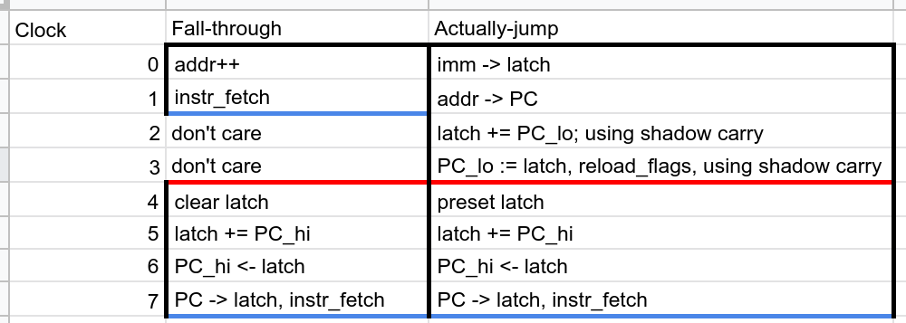
Note that after the fall-through case is handled, it contains code that actually does the jump.
It is never executed in the fall-through case, as the fall-through case is already finished by then.
Also note that reload_flags uses the sign bit of the last value read from memory instead of the sign flag from the ALU.
Let’s look at the fall-through case:
- Line 30: We increment the address latch, to skip over the immediate
- Line 31: We do a normal instruction fetch
- Line 80-86: This specifies when the fall-through code should be generated. It enumerates all jump opcodes, placing the code whenever the condition matches (by comparing to
bool(n), we emit the fall-through code when the jump matches and we're in “negated” mode, which means that we don’t actually match). Again, we already have the code for the instruction fetch, soauto_ifisFalse.
Now, the more complicated case where we actually jump:
- Line 20: We load the immediate to the latch. We update the
imm_signstate depending on the sign of the immediate. - Line 22: The latch, pointing at the next instruction (a
jumpby 0 would jump there, i.e. be anop. Ajump -2is an endless loop) is saved in the PC register - Line 24: We add the
PC_LOto the latch, storing the carry in the shadow carry flag. - Line 25-26: We move the latch back to
PC_LO. The lower PC now already has theimm8added to it. We now need to add-with-carry either0x00or0xffto the upper half of the PC. Thus, wereload_flags, and then implement the sign-extending. Since the last memory access was for the immediate, the sign bit input to the control word ROM will be uses, since it is still stored inimm_sign.
For sign-extending, we look at the flags set by the addition of PC_LO and the immediate. The signed flag will be set depending on the sign of the immediate, while the carry flag is the carry resulting from the addition.
- If the signed flag is not set (i.e. a sign extension is not necessary, as the immediate is non-negative), and the carry-flag is not set, the upper PC does not actually need to change, since we would just add
0x00, and the carry is also 0. - If the signed flag is set (i.e. a sign extension is necessary), and the carry flag also is set, then we would need to add
0xffto the upper PC, and additionally add 1 because the carry flag is set. This will actually be a no-op, as wrap around to exactly the value we started ad, so we can also do nothing in this case. - If the signed flag is set, and the carry flag is not, then we actually need to do a sign-extension, i.e. add
0xffto the upper PC and thus subtract 1 from the upper PC. - If the signed flag is not set, but the carry flag is, then we do not need to do a sign extension, but still handle the carry by increasing the upper PC by 1.
Note that the reason for the first two cases in the case distinction is just that this makes the common case where we do not need to adjust the upper PC faster. We could always simply look at the signed flag, and do an add-with-carry, which then actually performs no-op additions.
Let’s continue from where we stopped after reload_flags.
We are now in one of three tracks, depending on whether the upper PC needs to be decreased, increased or not changed.
The framework supports this by letting the user specify a start value for the microinstruction counter (ctr_start).
Hence, the instruction function does not necessarily define entire instructions, but instruction snippets which compose to the entire instruction.
In our case, the snippets for the three tracks are called jcc imm8s16 sext0, jcc imm8s16 sext1 and jcc imm8s16 no_sext.
The no_sext case is simpler, we describe it first:
- Line 77: As the upper PC does not need to change, and the lower PC is already computed, we just move the PC to the latch, and fetch and continue to our next opcode. This can happen in one cycle, as the address latch is level-triggered and will immediately propagate the PC once the control lines are stable. Thus, the jump is done.
The sext0 and sext1 cases are similar:
- Line 51 / 64: If we need to increase the PC, we clear the ALU latch, which sets all bits to 0. Otherwise, we do a
PRESET, which sets all bits to 1. - Line 52 / 65: We add the
PC_HIto the latch, using the shadow carry. Note that this could just be a regular add without carry in line 65. The result is saved in the latch. - Line 53 / 66: We move the result back to the
PC_HI. - Line 54 / 67: We move the PC to the latch and fetch the next instruction.
As can be seen in line 55, 68, and 78, we put the code after the reload_flags at all opcodes, but with a specific temporal offset, so that it is placed exactly as indicated in the diagram above.
prefix_a16
instruction("prefix_a16", opcode(0b10_000_000), [ p(CLine.set_addr16) | instruction_fetch,], auto_if=False)This is a seemingly normal instruction fetch. However, the prefix_a16 latch will be active during the next instruction.
This causes memory instructions to access IO devices instead of normal memory.
This may result in a bus request, which is described along with hardware interrupts.
add acc, [pi]
class AluOperation(IntEnum): CLEAR = 0 # HACK ALERT: # 74382 implements A-B as operation 1 and B-A as operation 2. # We've mistakenly switched A and B around on the ALU bread board, # and thus we're simply switching the operands around here. DBUS_MINUS_LATCH = 2 LATCH_MINUS_DBUS = 1 ADD = 3 XOR = 4 OR = 5 AND = 6 PRESET = 7 def state(self) -> CState: return CState.set_int(self.value, [ CLine.alu_operation_0, CLine.alu_operation_1, CLine.alu_operation_2, ])class AluCarrySelect(IntEnum): CARRY = 0 NONE = 1 SIGN = 2 SERIAL = 3 def state(self) -> CState: return CState.set_int(self.value, [ CLine.alu_carry_select_0, CLine.alu_carry_select_1, ])alu_cmp_base = CState( p=(CLine.alu_update_flags), n=(CLine.alu_shift_right | CLine.alu_use_shadow_carry | CLine.alu_update_just_carry | CLine.alu_set_flags_raw | CLine.alu_zero_flag_and))alu_op_base = alu_cmp_base | p(CLine.alu_accu_set)for i, op in enumerate(IsaBinOp): instruction(f"{op.value} acc, [pi]", opcode(0b01_000_110 | i << 3), [ accu_to_latch | UarchReg16.PC.from_addr(), UarchReg16.PI.to_addr(), op.state() | mem_to_dbus, UarchReg16.PC.to_addr() | instruction_fetch, ], auto_if=False)This instruction is actually generalized over all for i, op in enumerate(IsaBinOp).
For ADD, the state() method returns alu_op_base | AluOperation.ADD.state() | AluCarrySelect.NONE.state().
As can be seen, this sets the alu_carry_select and alu_operation control line bundles appropriately.
- Line 45: We save the address latch (i.e. the next instruction) in the
PCregister. - Line 46: We move
PIto the latch. - Line 47: We execute the specified ALU operation between the latch and the bus. Concretely, this means that for
ADD- The
alu_operationcontrol line is set to0x3 - The
alu_carry_selectcontrol line is set to0x1 alu_update_flagsis set, so the flags get updatedalu_shift_rightis not set, as this is not a shiftalu_use_shadow_carryis also not set, as we want to affect the proper carryalu_update_just_carryis also not set, as we do want to set all flagsalu_set_flags_rawis also not set, because this would load the flags from the busalu_zero_flag_andis also not set. If true, it would AND the old and the new zero flag, instead of just overwriting.alu_accu_setis set, so that the result gets written back to the accu.mem_to_dbusis set, so that the other operand is read from memory. Interestingly, this means that the operation is performed twice in case of a bus request. However, since the inputs remain stable, in particular the latch does not change, this is not an issue. We just overwrite the accu’s first, incorrect result with the second, correct result at the second execution.
- The
- Line 48: We move the
PCback and do an instruction fetch.
add ab, imm8s16
alu_add = AluOperation.ADD.state() | AluCarrySelect.NONE.state() | CState( p=(CLine.alu_latch_set | CLine.alu_update_flags), n=(CLine.alu_zero_flag_and | CLine.alu_set_flags_raw | CLine.alu_update_just_carry | CLine.alu_shift_right | CLine.alu_use_shadow_carry),)# Intended for upper 8 bitsalu_adc = AluOperation.ADD.state() | AluCarrySelect.CARRY.state() | CState( p=(CLine.alu_latch_set | CLine.alu_update_flags | CLine.alu_zero_flag_and), n=(CLine.alu_set_flags_raw | CLine.alu_update_just_carry | CLine.alu_shift_right | CLine.alu_use_shadow_carry),)for w, dest in enumerate(IsaReg16): add_imm8s16_start = [ dest.value.lo().to_dbus() | dbus_to_alu_latch, load_imm | alu_add, alu_latch_to_dbus | dest.value.lo().from_dbus() | CState(p=CLine.reload_flags, n=CLine.alu_use_shadow_carry), ] instruction(f"add {dest.name}, imm8s16", opcode(0b11_10_10_00 | w), add_imm8s16_start, auto_if=False) # Note that we cannot skip dealing with the upper byte because we care about # the flags. instruction(f"add {dest.name}, imm8s16 sext0", ( (0b11_10_10_00 | w) << OPCODE_LSB | f << FLAGS_LSB for f in range(1 << NUM_FLAGS) if f & (1 << SF_NUM) == 0 ), [ clear_alu_latch, dest.value.hi().to_dbus() | alu_adc, alu_latch_to_dbus | dest.value.hi().from_dbus(), instruction_fetch, ], auto_if=False, ctr_start=len(add_imm8s16_start)) instruction(f"add {dest.name}, imm8s16 sext1", ( (0b11_10_10_00 | w) << OPCODE_LSB | f << FLAGS_LSB for f in range(1 << NUM_FLAGS) if f & (1 << SF_NUM) != 0 ), [ preset_alu_latch, dest.value.hi().to_dbus() | alu_adc, alu_latch_to_dbus | dest.value.hi().from_dbus(), instruction_fetch, ], auto_if=False, ctr_start=len(add_imm8s16_start))Here, we've got a sign-extending instruction again. Compared to a conditional jump, things are a bit different though.
In particular
- We do not have to initially look at the condition code to see whether the operation is really necessary. The add is always executed.
- Since we care about the flags for the result, we cannot elide the addition of the upper 8 bits as done in the
no_sextcase above.
Let’s look at the execution:
- Line 15: We move the lower part of the 16-bit register we want to add to the latch.
This sets the
sign_immlatch. - Line 16: We add the immediate to the latch, using the normal flags (not the shadow carry). The sign bit is now set to
sign_imm, i.e. the sign of the immediate. - Line 17-18: We move the latch back to the lower part of the register we wanted to add to. Again, the lower part is now proper. We now consider the sign bit, to figure out if we need to add
0x00or to0xffto the higher part of the registers. Thus, we reload the flags and continue execution depending on whether the signed flag was set or not set. - Line 30 / 40: We set the latch to
0x00if the signed flag is not set (line 30), and to0xffif it is set (line 40). - Line 31 / 41: We add the higher part of the register to the latch, storing the result in the latch. We also AND the current zero flag with the new zero flag, so that it is zero iff the entire 16 bits of the result are zero. The other flags are correct, since they only look at the carry flag and the highest bit of the result.
- Line 32 / 42: We move the latch back to the higher part of the register.
- Line 33 / 43: We do a normal instruction fetch.
Interrupts
instruction("hardware interrupt", ( opcode << OPCODE_LSB | 1 << INT_BIT | flags << FLAGS_LSB for opcode in range(0x01, 0x100) # do not override reset for flags in range(1 << NUM_FLAGS)), [ # Save acc in Z accu_to_dbus | UarchReg8.Z.from_dbus() | clear_alu_latch # As the PC points to the byte after the opcode where we want to continue # the execution, we need to decrement the PC by one first. | postdecrement_addr, # Save the PC in WX UarchReg16.WX.from_addr() | p(CLine.set_addr16), # Jump to 0x0000, turn on INTACK UarchReg8.PC_LO.from_dbus() | zero_to_dbus, UarchReg8.PC_HI.from_dbus() | p(CLine.toggle_intack) | zero_to_dbus, # Load the interrupt code into acc mem_to_dbus | UarchReg16.PC.to_addr() | dbus_to_accu_with_empty_latch, # Save the alu flags in Y p(CLine.alu_flags_to_dbus) | UarchReg8.Y.from_dbus(), # turn off INTACK (conflicts with *_to_dbus) p(CLine.toggle_intack), # Turn off interrupts, fetch instruction at 0x0000 p(CLine.set_interrupt_inhibit) | UarchReg16.PC.to_addr() | instruction_fetch,], auto_if=False)Line 1 defines the “opcode”.
In this case, the code executing is of course not responsible for a specific instruction, but the code still expects a name here.
The next line defines all opcodes for which this is mapped, which are many. Importantly, the instruction with opcode 0 (reset) is not mapped, since reset is also executed when an interrupt is pending.
Apart from this, the interrupt code will be executed for all other opcodes and all other flag combinations, as long as the interrupt flag is on (line 2, 3).
Then, we define the actual instructions:
- Line 6-10: First, we save the accu in register Z (this is a shadow register). We also clear the ALU latch, to later move things into the accu. Finally, we decrement the latch (which contains the PC). This is necessary, since we have the invariant that the address stored in the latch always is the address of the current instruction +1 when starting.
- Line 11-12: Next, we save the PC in WX, which is another shadow register.
The actual PC will remain in WX until we execute an
iret, when it will be restored. This means that nested interrupts are not supported. Further, we set the addr16 latch. This will later allow us to read the interrupt number, which is canonically “stored” in IO memory, address00. - Line 13-14: We set
PC_LOto zero. - Line 15: We set
PC_HIto zero. Also, we toggleintack, which is now high. This is part of the interrupt procedure and tells the device which caused this interrupt that it can pull the interrupt signal low again. - Line 16-17: We load from memory. Since
mem_to_dbusis used, which just desugars toregular_load, and sinceaddr16is set, we execute a bus request, since the corresponding latch is set. This means thatBUS_REQUESTbecomes high. Further, the address needs to be0x0000, because this is what IO devices expect. This is the most complicated part of the control unit and further documented here. - Line 16-17: Since we are doing a bus request, we freeze the microinstruction counter for one cycle. This means that we basically load into the accu a second time, but this time the interrupting device has had time to write the interrupt number to the bus.
- Line 18-19: The accu now contains the interrupt number. We still need to save the flags, so that we can later restore them.
- Line 20-21: We disable interrupt_acknowledge. Since this control line is mutually exclusive with the control lines directing access to the bus, this has to happen separately.
- Line 22-24: We now set interrupt_inhibit, and move
0000(which was previously stored to PC) to the address latch. We then execute an instruction fetch, which means that we load the next instruction and continue from there.
Line 25 further specifies that we do not want the automatic instruction fetch that this python framework would otherwise append to the “instruction.”
We additionally (to the normal instruction_fetch) have to set the interrupt inhibit flag.
We also move the PC to the latch again, but this is actually unnecessary since the latch did not change since line 17.
Note that the precise output of all ADDR16-related control lines for step 5 to 6 is discussed here.