µArch Simulator
The µArch Simulator implements a faithful HDL model of the control, register, memory, and ALU schematics. It was developed by Florian with contributions by Nils and JoHo.
Installation
The hardware modules are described using the Amaranth hardware description language (HDL).
Install the amaranth package into your user environment (pip3 install --user amaranth) or use a virtual environment if you don't want to pollute your user environment:
python3 -m venv venv
source venv/bin/activate.sh
pip3 install amaranth
Usage
hdl/board.py is the main entry-point for the simulator and includes a small CLI:
⋊> ~/_/u/8/hdl on main ⨯ python3 board.py --help
usage: board.py [-h] --rom ROM [--microcode UCODE.CSV] [--trace TRACE] [--write-vcd]

SaarPU µArch Simulator

options:
  -h, --help            show this help message and exit
  --rom ROM             Path to rom file (bin or .s) (default: None)
  --microcode UCODE.CSV Path to microcode.csv (default: <autogenerate>)
  --trace TRACE         Kind of trace (isa/uarch) (default: isa)
  --write-vcd           Write out a vcd trace of the simulation (board.vcd) (default: False)
The simulator currently supports two output formats. One for microarchitecture debugging, and a one-line-per-instruction trace that hides the inner workings:
⋊> ~/_/u/8bit-main on main ⨯ python3 hdl/board.py --trace=isa --rom=isa/bootrom-test.bin
0x0000: reset                   (ab=0x0000 cd=0x0000 pi=0x0000 sp=0x0000) flags: ____ accu: 0x00
0x0000: mov sp, imm16           (ab=0x0000 cd=0x0000 pi=0x0000 sp=0x0000) flags: ____ accu: 0x00
0x0003: hlt                     (ab=0x0000 cd=0x0000 pi=0x0000 sp=0xf000) flags: ____ accu: 0x00
halted
Microarch debugging trace example
⋊> ~/_/u/8/hdl on main ⨯ python3 board.py --trace=uarch --rom=../isa/bootrom-test.bin
=========== <init> ===========
regs: ab=0x0000 cd=0x0000 pi=0x0000 sp=0x0000 pc=0x0000 uv=0x0000 wx=0x0000 yz=0x0000
accu: 0 latch: 0 flags: ____
büße: data=0x00 addr=0x0000
inst: opcode=0xff 'reset' (#0)
ctrl:

regs: ab=0x0000 cd=0x0000 pi=0x0000 sp=0x0000 pc=0x0000 uv=0x0000 wx=0x0000 yz=0x0000
accu: 0 latch: 0 flags: ____
büße: data=0x00 addr=0x0000
inst: opcode=0xff 'reset' (#1)
ctrl: alu_accu_set, alu_latch_set

regs: ab=0x0000 cd=0x0000 pi=0x0000 sp=0x0000 pc=0x0000 uv=0x0000 wx=0x0000 yz=0x0000
accu: 0 latch: 0 flags: ____
büße: data=0x00 addr=0x0000
inst: opcode=0xff 'reset' (#2)
ctrl: reg_w_2, reg_w_sel_0

regs: ab=0x0000 cd=0x0000 pi=0x0000 sp=0x0000 pc=0x0000 uv=0x0000 wx=0x0000 yz=0x0000
accu: 0 latch: 0 flags: ____
büße: data=0x00 addr=0x0000
inst: opcode=0xff 'reset' (#3)
ctrl: reg_w_2, reg_w_sel_1

regs: ab=0x0000 cd=0x0000 pi=0x0000 sp=0x0000 pc=0x0000 uv=0x0000 wx=0x0000 yz=0x0000
accu: 0 latch: 0 flags: ____
büße: data=0xef addr=0x0000
inst: opcode=0xff 'reset' (#4)
ctrl: reg_latch_load, reg_r_2, reset_uinst_counter

========= pc: 0x0000 =========
regs: ab=0x0000 cd=0x0000 pi=0x0000 sp=0x0000 pc=0x0000 uv=0x0000 wx=0x0000 yz=0x0000
accu: 0 latch: 0 flags: ____
büße: data=0x00 addr=0x0000
inst: opcode=0xef 'mov sp, imm16' (#0)
ctrl: reg_latch_count, reg_latch_up

regs: ab=0x0000 cd=0x0000 pi=0x0000 sp=0x0000 pc=0x0000 uv=0x0000 wx=0x0000 yz=0x0000
accu: 0 latch: 0 flags: ____
büße: data=0x00 addr=0x0001
inst: opcode=0xef 'mov sp, imm16' (#1)
ctrl: reg_latch_count, reg_latch_up, reg_w_0, reg_w_1, reg_w_sel_0, regular_load

regs: ab=0x0000 cd=0x0000 pi=0x0000 sp=0x0000 pc=0x0000 uv=0x0000 wx=0x0000 yz=0x0000
accu: 0 latch: 0 flags: ____
büße: data=0xf0 addr=0x0002
inst: opcode=0xef 'mov sp, imm16' (#2)
ctrl: reg_latch_count, reg_latch_up, reg_w_0, reg_w_1, reg_w_sel_1, regular_load

regs: ab=0x0000 cd=0x0000 pi=0x0000 sp=0xf000 pc=0x0000 uv=0x0000 wx=0x0000 yz=0x0000
accu: 0 latch: 0 flags: ____
büße: data=0xb6 addr=0x0003
inst: opcode=0xef 'mov sp, imm16' (#3)
ctrl: reset_uinst_counter

========= pc: 0x0003 =========
regs: ab=0x0000 cd=0x0000 pi=0x0000 sp=0xf000 pc=0x0000 uv=0x0000 wx=0x0000 yz=0x0000
accu: 0 latch: 0 flags: ____
büße: data=0x00 addr=0x0003
inst: opcode=0xb6 'hlt' (#0)
ctrl: hlt, reg_latch_count, reg_latch_up

halted
Note: If you’ve got customasm installed (cargo install customasm), you can also specify assembly files with --rom directly
⋊> ~/_/u/8/hdl on main ⨯ python3 board.py --trace=isa --rom=../isa/isa-test-stack.s
customasm v0.11.14 (x86_64-unknown-linux-gnu)
assembling `../isa/isa.s`...
assembling `../isa/isa-test-stack.s`...
success after 1 iteration

 outp | addr | data

  0:0 |    0 | ef 00 f0       ; mov sp, 0xf000
  3:0 |    3 | 3c             ; push acc
[...]
 76:0 |   76 | b6             ; hlt

0x0000: reset                   (ab=0x0000 cd=0x0000 pi=0x0000 sp=0x0000) flags: ____ accu: 0x00
0x0000: mov sp, imm16           (ab=0x0000 cd=0x0000 pi=0x0000 sp=0x0000) flags: ____ accu: 0x00
0x0003: push acc                (ab=0x0000 cd=0x0000 pi=0x0000 sp=0xf000) flags: ____ accu: 0x00
[...]
0x0076: hlt                     (ab=0xf000 cd=0x0123 pi=0x4567 sp=0xf000) flags: _Z_C accu: 0x0f
halted
Architecture
The microarchitectural simulator includes a faithful hardware model of the ALU, register, memory and control schematics.
These modules live in separate Python files and include small isolated unit tests. (i.e. run rom.py or alu_74382.py to sanity-check individual subcomponents).
In a few cases, the HDL logic is a bit simpler than the real schematics -- probably because we're not bound to the component and space restrictions.
In other cases, the underlying restrictions of the Amaranth HDL prevent us from accurately modelling the schematics and we require workarounds. (i.e. BusTransceiver.py has two sets of pins for each side because Amaranth doesn't support tri-state signals)
Clock Domains
Our processor design performs work in two distinct phases: A "control" phase, where execution is prepared and control lines are set, and a "compute" phase, where the instruction is executed (i.e. latches and registers are set based on the current control lines). In hardware, this is realized by using both the rising and falling edge of the clock signal, with some oddballs that require delayed clocks. This design is extensively documented on the control/clock page.
Amaranth, in principle, abstracts away these hardware timing details. Combinatorial logic and connection lines settle instantly, and registers are updated synchronously.
This greatly simplifies simulation and model complexity, but our designs depend on some of these details.
To decouple the control and computation logic, and to model level-triggered updates, we introduce a few phases ("clock domains") to our simulation lifecycle:
ctrl: The microarchitectural control word is updated here, as well as most other control logic and the control lines. This corresponds to the falling edge of our hardware clock line.presync: To model level-triggered preload-and-count chips (74-191), we use thepresyncphase to increment the address latch before the "execution" phase, but after the control lines have been updated.sync: In this phase, computation has settled, and the results are saved to registers.
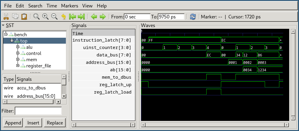
The screenshot below shows some of the HDL model's signals and register while executing mov ab, 0x1234.
How This Helps
Reverse Engineering / Understanding IC Chip Behavior
While most of the 74-series data-sheets include a basic description of the chip functionality, the documentation can be quite unclear at times. The 74-382 ALU chip is particularly bad at this. Try searching for a specification the carry and overflow outputs when using the chip in different function modes...
To obtain a complete specification for the ALU chip, we dumped a full truth table (two 4-bit operands, 3-bit function mode, carry in bit) and tried to match it in the HDL model. This process uncovered some surprising behavior, in particular, that the carry input bit is inverted during subtraction operations, and allowed us to fully specify each operation's effects on the ALU flags, and avoid broken subtract-with-carry.
Differential Testing
We applied extensive randomized differential testing between the HDL model and the control and ALU components. The process is detailed in the control/testing page.
Roughly half of the bugs we found were actually issues with the HDL model. While this is not a great true-positive rate, those bugs are easy to fix and thinking about these implementation details greatly improves the understanding of the whole system :)
Microcode and Architecture Design
Developing software is a lot more convenient, and easier to collaborate on, than wiring up ICs on a breadboard. The HDL model allowed us to test and verify our designs and microcode implementation before actually building anything. We built up a test suite of ISA verification snippets, that we executed both on the real build, and in the simulator. The test suite is covered here.