Graphics Hardware
Structure
The graphics unit consists of three submodules that interact with each other:
- The counter module, consisting of the clock and counters for
xandy, as well as the comparators for generatinghsync,vsync, and the blanking intervals - The output module that handles the actual image generation
- The memory module, which contains the two RAM chips and handles the switching of CPU and GPU access
As the output module needs access to both the counter and the memory module, it is located in the middle in the final build.
Integration With the Full Build
The graphics unit, like other I/O devices, is not placed in a fixed location in the final build. Instead, it can be moved around separately or even disconnected when not needed.
When the graphics unit is used, it must be connected to
- The 16-bit address bus
- The 8-bit data bus
BUSREQIO/MEM_FROM_DBUSADDR16FB_SELand~FB_SEL
All these connect to the memory submodule of the graphics unit, as it is the only part that communicates with the CPU.
The inverted FB_SEL line seems redundant. However, we chose to use this instead of an additional chip, as there was an unused D-flip-flop in the control unit.
It is not important whether FB_SEL is low or high initially, which means that it can be safely swapped with the inverted version.
In the final build, the inverted FB_SEL line was very noisy for no apparent reason (other than a very long cable) and had to be smoothed with a capacitor.
After the graphics unit was designed and built, the I/O group decided that all their devices would use a 30-pin cable that carries the two busses and all necessary control signals (including FB_SEL).
However, this cable does not carry ADDR16 - instead, the address on this cable is set to zero when ADDR16 is not set.
We decided to use their cable as well, as it was already connected to the CPU and we did not want to do this work twice.
As the graphics unit only listens to addresses where the highest bit on the address bus is set (in addition to ADDR16), we could just set ADDR16 to high instead of connecting it to the CPU.
Lessons Learned
We encountered several issues while building the graphics unit, most notably:
- Breadboard power rails are not very reliable, especially when multiple are connected together. A slightly unstable power rail is very problematic for active-low signals (like write enable). In the end, we could only get everything stable by using two power rails, one on each side.
- The Keyestudio Mega 2560's outputs were not stable enough for our purposes. When they were high, they would still dip low enough to be recognized as low, causing many spurious writes.
These issues only occurred with the Mega 2560, and do not persist in the final build. We did not try original Arduinos or other clones. - If a signal is too noisy, the oscilloscope's capacitance can smooth it out, hiding the issue. If connecting the oscilloscope makes things work, this might be the cause.
- VGA timings don't need to be exact, however, it can be trial and error to see what deviance a monitor accepts and at what point it rejects the signal.
Known Issues
Our build starts outputting image data too soon (before the intended image in both x and y direction). We did not find a way to resolve this without adding more comparators, which would require more space. As a workaround, the image can be manually adjusted in the monitor settings.
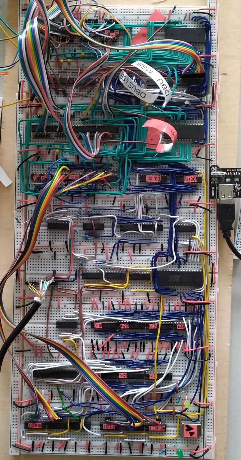
Build Photo