Counter Submodule
The counter module is responsible for generating x & y addresses to read image pixels or characters from the framebuffers, as-well-as generating the active low hsync & vsync signals for the VGA signal.
VGA Protocol Timings
Taken from tinyvga.com. A VGA signal works using 5 wires, three for the color channels, one for the active-low hsync signal, and one for the active-low vsync signal. The producer varies the voltage values on the color channels in the range of 0-0.7V. The mode, i.e. pixel resolution and refresh frequency, depends on the timing of the two sync signals. The consuming monitor therefore first determines the mode of the data that it receives and will then sample the color channels once per pixel accordingly.
The pixel clock for our chosen mode should be 25.175MHz, but a 25MHz clock works just fine. The people that built the Gigatron also had the same experience, using a clock with a slightly different frequency.
Each line consists of 640 pixels and a short "porch" period at the end, where no pixel data should be sent. The "porch" period (~send pixels x) includes a sync pulse hsync which has a strictly shorter duration.
Since our image pixels are 4 monitor pixels wide, we divide all the pixel values by 4 in the table below. The x counter is then compared against these values to drive the send pixels x and hsync signals.
Analogously, each frame consists of 525 lines, of which 480 are visible. After the visible part, there is a short period where no pixel data should be sent. Located in this ~send pixels y period, there is the sync pulse vsync which has a strictly shorter duration.
Since our virtual pixels are 4 monitor pixels high, we divide all the line amounts by 4 in the table below. The y counter is then compared against these values to drive the send pixels y and vsync signals.
Horizontal timing (line)
Polarity of horizontal sync pulse is negative.
| Scanline part | Pixels | Virtual Pixels | Time [µs] |
|---|---|---|---|
| Visible area | 640 | 160 | 25.422045680238 |
| Front porch | 16 | 4 | 0.63555114200596 |
| Sync pulse | 96 | 24 | 3.8133068520357 |
| Back porch | 48 | 12 | 1.9066534260179 |
| Whole line | 800 | 200 | 31.777557100298 |
Vertical timing (frame)
Polarity of vertical sync pulse is negative.
| Frame part | Lines | Virtual Lines | Time [ms] |
|---|---|---|---|
| Visible area | 480 | 120 | 15.253227408143 |
| Front porch | 10 | ~2 | 0.31777557100298 |
| Sync pulse | 2 | 0.5 | 0.063555114200596 |
| Back porch | 33 | ~8 | 1.0486593843098 |
| Whole frame | 525 | ~131 | 16.683217477656 |
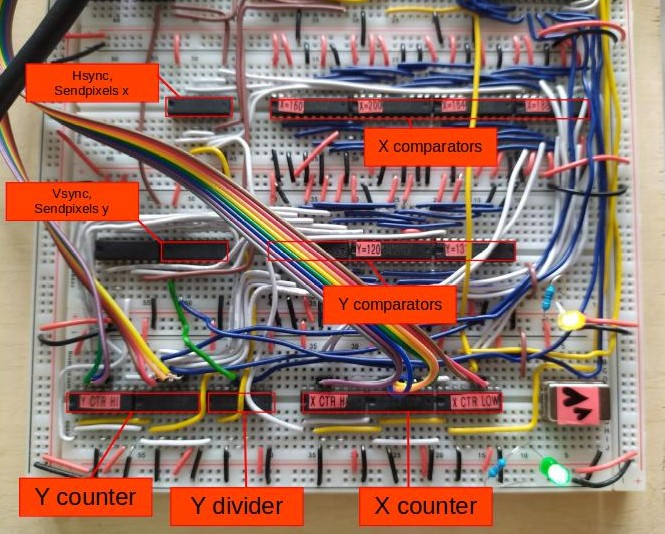
Implementation
The 25 MHz clock drives a couple of chained 161 counters, which results in several clock outputs that have successively halved frequencies.
Since our image's virtual pixels are 4 monitor pixels wide, the x address should be incremented on each 4th rising clock edge, therefore the x output starts at the 3rd output pin of the first counter. For the same reason, the y address should be incremented on each 4th line that was completed. For this we use the "Y divider counter" whose 2nd output pin is connected to the actual y counters.
The x and y addresses are fed into several comparators. These are used to compute the signals needed for the VGA protocol. We list the comparators and their effect below. The counter module also outputs what we call the "physical y" address, which counts the actual pixel lines. This is needed for our full resolution text mode.
A line ends at x = 200. However, in order for the image mode switching to work properly (and not switch one row too late), we already need to increment y to the next row before the mode selection byte is read.
For this reason, the y counter is incremented when send pixels x is unset (at x=160).
Theoretically, this interferes with the proper timing of vsync, but our monitor seems to tolerate this deviation.
Comparators
Here, set means applying high voltage and unset means applying low voltage.
X=160 ⇾ unset
send pixels xX=164 ⇾ unset
hsyncX=188 ⇾ set
hsyncX=200 ⇾ set
send pixels xY=120 ⇾ unset
send pixels yY=122 ⇾ unset
vsyncY=131 ⇾ set
send pixels y
Note that, according to the protocol, vsync would have to be set at Y=122.5 again. We tried Y=123, but that deviated too much and the monitor did not accept the signal.
So we save one comparator and set vsync using the 2nd output of the "Y divider" counter, which is the same as counting Y in 0.5 increments.
Schematics

In the Build